
The World of Model Rockets: A Guide to Building and Launching Your Own Rocket
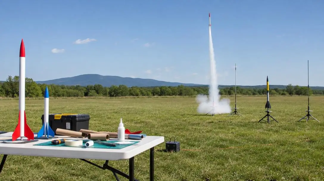
Model rocketry offers an approachable, thrilling gateway into the fundamentals of aeronautics, structural engineering, and hands-on craftsmanship. By taking lightweight materials and assembling them with careful balance, hobbyists of all ages can transform basic workshop supplies into functional aerial vehicles. Unlike massive commercial or government space vehicles, introductory model rockets are designed to be constructed without industrial machinery or specialized production facilities—an ordinary kitchen table or workbench offers plenty of space to assemble these high-flying craft.
Mastering this hobby requires a solid grasp of internal and external components, strict adherence to established safety guidelines, and a methodical approach to pre-flight preparation. When builders understand the science behind flight stability and follow disciplined construction and launching protocols, every mission delivers an exhilarating, dependable flight from pad liftoff to soft recovery.
Key takeaways
- Model rockets rely on four core structural components—the nose cone, body tube, stabilizing fins, and engine mount—working together to ensure stable flight and successful recovery.
- Dedicated ground support equipment, including a stable launch pad with a blast deflector and an electrically interlocked launch controller with a safety key, is required for safe ignition.
- Proper launch site selection demands an expansive outdoor area free from trees, residential structures, and overhead power lines.
- Applying thin, uniform paint layers enhances aerial visibility without adding dead weight, while keeping the nose cone shoulder unpainted preserves recovery system deployment.
- Joining organized rocketry clubs and competitions provides access to standardized safety codes, structured launch ranges, and technical mentorship.
The four core structural components of a model rocket
Every standard model rocket balances aerodynamic forces and mechanical stresses across four interconnected structural elements. When aligned and bonded properly, these parts ensure the vehicle ascends vertically under power, tracks true against atmospheric currents, and deploys its recovery equipment at the peak of flight.
The Nose Cone
Positioned at the forward tip of the airframe, the nose cone provides a sculpted aerodynamic surface designed to part the air and minimize atmospheric drag as the rocket accelerates skyward. Its base features a circular shoulder that slides snugly into the upper rim of the body tube. To function correctly during recovery, this interface must remain secure enough to stay in place under high-speed acceleration while sliding out cleanly when the motor's internal ejection charge fires forward to release the parachute or streamer.
The Body Tube
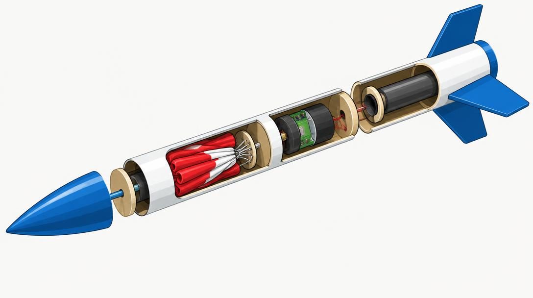
The body tube forms the primary structural spine of the rocket, consisting of a long, hollow, and lightweight cylinder. It serves as the physical housing that joins the nose cone at the front, the external stabilizing fins along the base, and the internal engine assembly inside the rear. The interior volume also stores the vehicle's recovery gear—such as parachutes or streamers—along with the flame-resistant recovery wadding that shields fragile recovery lines and canopies from hot motor gases.
The Fins
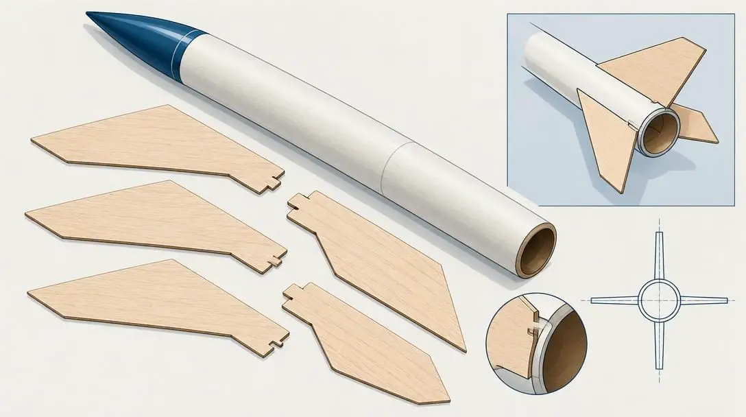
Mounted around the exterior base of the body tube, the fins act as the primary aerodynamic stabilizers. As the rocket climbs through the air, ambient airflow passes over these flat surfaces, exerting corrective forces whenever the rocket begins to tilt. When properly aligned and distributed evenly around the tube's circumference, the fins position the vehicle's center of pressure safely behind its center of gravity. This vital aerodynamic relationship prevents mid-air tumbling and holds the vehicle on a straight, predictable trajectory.
The Engine Mount

The engine mount is an internal sub-assembly installed inside the rear section of the body tube to anchor the solid-propellant rocket motor. During the burn phase, the motor produces significant forward kinetic thrust. Centering rings, an engine block, and a retaining clip absorb this force and transfer it directly into the body tube, propelling the rocket into the sky without dislodging the motor or damaging the surrounding cardboard chassis.
| Component | Airframe Location | Primary Function | Key Maintenance or Assembly Consideration |
|---|---|---|---|
| Nose Cone | Forward apex | Reduces atmospheric drag; seals recovery bay | Must fit snugly yet slide out smoothly without binding |
| Body Tube | Central fuselage | Unifies structural components; houses recovery system | Must remain straight, dent-free, and clean inside |
| Fins | Exterior rear base | Maintains directional stability; offsets rotation | Must be aligned parallel to the centerline of the body tube |
| Engine Mount | Interior rear section | Secures solid-propellant motor; transfers thrust | Requires complete adhesive curing around centering rings |
Ground support equipment: Preparing the launch pad
Model rockets cannot simply be placed on bare dirt and lit with an open flame; they require dedicated ground support infrastructure to establish initial flight velocity and initiate remote electrical ignition safely.
The Launch Pad
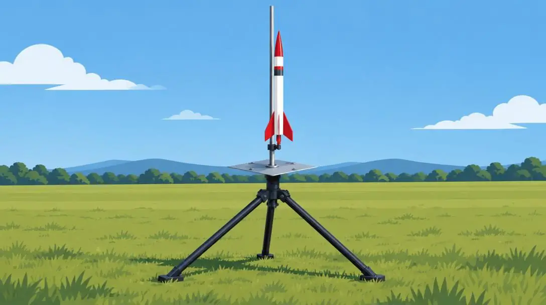
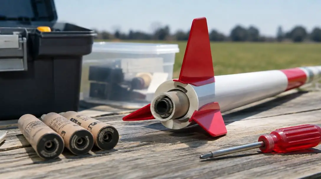
The launch pad provides a sturdy, level base that bears the full weight of the rocket prior to liftoff. Its central feature is an elongated vertical guide mechanism, known as the launch rod, which passes through a small launch lug glued along the rocket's body tube. During the initial split second of ignition, before the rocket builds sufficient airspeed for its fins to stabilize flight, the launch rod guides the vehicle in a straight upward orientation. Beneath the engine nozzle sits a durable metal blast deflector plate, which redirects intense rocket exhaust away from the underlying terrain to prevent scorching or fire hazards.
The Launch Controller
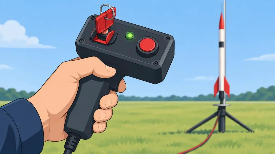
Operating from a safe distance through an extended wiring harness, the launch controller is a handheld electronic console that regulates electrical current to the rocket engine's igniter. Safety interlocks are engineered directly into the device: a removable safety key must be manually inserted into the console to close the circuit and arm the system. Once inserted, a continuity indicator illuminates to verify an unbroken electrical path. Depressing the launch button while the key is engaged routes current down the leads to heat the igniter and light the solid propellant remotely.
Essential safety gear and launch site criteria
Safe operation is the foundation of model rocketry. Consistent safety discipline protects builders from construction injuries and ensures spectators enjoy a controlled, hazard-free flight experience.
Every builder must assemble essential protective items before beginning construction or heading to the field:
- Safety glasses: Protect the eyes from chemical splashes during gluing and painting, as well as high-speed debris, sparks, or propellant fragments during active launch operations.
- Gloves: Shield skin against harsh adhesives and solvent-based finishing coatings during assembly, and guard against heat when handling hot motor casings immediately following touchdown.
- Fire extinguisher: Keep a fully charged, readily accessible extinguisher adjacent to the launch controller to extinguish any dry brush or grass that might catch stray sparks.
- Safe workspace: Set up assembly areas in well-ventilated, uncluttered rooms free of open flames, combustible chemicals, or household hazards.
Selecting an appropriate launch field is equally critical. Launches must take place in broad, unobstructed outdoor areas far from common environmental obstacles:
- Houses and buildings: Operating well clear of structures safeguards private property against accidental impacts and maintains unobstructed sightlines for range officers.
- Trees: Open acreage prevents descending parachutes, recovery streamers, and airframes from snagging high in branches beyond reach.
- Overhead power lines: Keeping generous clearance from power lines eliminates electrocution hazards and prevents costly utility disruptions.
Step-by-step practical guide: Assembling your rocket
While individual commercial rocket kits may feature slight variations, following a systematic, step-by-step construction order guarantees durable glue joints, proper aerodynamic balance, and clean recovery deployment.
- Prepare the workspace: Clear a level, flat work surface, lay down protective paper or cutting mats, and gather basic supplies, including adhesives, hobby blades, sanding blocks, safety glasses, and gloves. Read the instruction manual thoroughly before opening glue containers.
- Assemble the engine mount: Glue the centering rings, forward engine block, and spring-steel engine hook onto the central engine tube according to the kit's exact measurements. Allow the adhesive joints to cure fully to handle peak thrust loads during liftoff.
- Install the engine mount into the body tube: Swab an internal ring of adhesive inside the rear of the body tube at the marked depth. Slide the engine mount assembly inside with a smooth, continuous motion, ensuring the centering rings create a uniform structural bond against the tube's interior wall.
- Attach the stabilizing fins: Bond the pre-cut fins to the rear exterior of the body tube. Space them evenly around the circumference, aligning each fin precisely parallel to the tube's central longitudinal axis to avoid induced aerodynamic roll or drift. Apply smooth glue fillets on both sides of every fin root joint for maximum strength.
- Install the nose cone and shock cord: Fasten the internal elastic shock cord to the interior wall of the body tube, anchor the opposite end to the nose cone, and slide the nose cone shoulder into the forward opening. Verify that the fit holds securely against gentle shaking but slides out smoothly when pulled.
Precise aerodynamic alignment during assembly ensures that air streams symmetrically over the fins, holding the ascending vehicle firmly on a vertical flight path.
Finishing, painting, and aerodynamics
Applying custom finishing techniques turns a basic cardboard and balsa assembly into a striking, personalized model. High-contrast paint schemes serve a practical purpose as well, making the rocket far easier to track visually through its burn phase, coast phase, and descent against white clouds or bright blue skies.
Achieving a high-performance finish requires a balance between aesthetic appeal and aerodynamic efficiency:
- Non-flammable finishes: Only apply non-combustible enamels, acrylics, and finishing accents that can withstand the heat generated by the motor and exhaust plume.
- Smooth, even coats: Spray paint in light, uniform coats rather than heavy, wet layers. Thick, dripping paint runs create asymmetrical drag profiles and add unnecessary dead weight at the nose or tail.
- Unpainted mating joints: Never apply paint, clear coat, or primer over the shoulder portion of the nose cone where it slides inside the upper body tube. Paint build-up inside this joint will bind the nose cone shut, preventing the internal ejection charge from deploying the parachute.
- Lightweight accents: Use self-adhesive stickers, dry-transfer decals, or markers to detail the airframe without upsetting the center of balance.
The launch day countdown and flight procedure
A rigorous launch sequence ensures that mechanical checks, spectator safety, and electrical systems operate in total coordination on the field.
- Inspect the launch site: Check the field for shifts in wind direction, wandering wildlife, and potential obstacles. Direct all spectators to stand behind the launch controller perimeter.
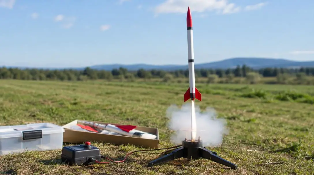
- Set up the launch pad: Position the tripod pad on firm, level ground. Check that the launch rod points vertically or slightly tilted downwind toward the open drop zone, and seat the metal blast deflector directly below the rocket exhaust location.
- Examine the vehicle: Inspect the assembled rocket for airframe cracks, loose fin fillets, or a tight nose cone. Pack flame-resistant recovery wadding into the upper body tube, fold the parachute or streamer loosely, insert the recovery gear, and seat the nose cone.
- Mount the rocket on the pad: Thread the rocket's launch lug down over the metal launch rod. Check that the craft glides freely along the full length of the rod without mechanical friction or binding.
- Install and wire the igniter: Insert the igniter into the engine nozzle until its coated tip touches the internal propellant grain. Lock it in place with the manufacturer's plug, then attach the launch controller's micro-clips to the two lead wires. Verify that the bare metal clips do not touch each other or the metal blast plate.
- Arm the launch controller: Retreat to the full length of the controller cable. Insert the safety interlock key into the controller and confirm that the continuity lamp glows bright red.
- Execute the countdown: Announce the countdown audibly to alert all nearby observers: 5, 4, 3, 2, 1!
- Launch and track: At zero, press and hold the launch button until the motor ignites. Keep your eyes on the vehicle through its powered boost, burnout coast, recovery deployment, and touchdown.
Troubleshooting common assembly and flight issues
When flight anomalies or electrical glitches occur, a logical, step-by-step diagnostic process allows hobbyists to isolate the cause and correct it safely.
Engine ignition failure: If the launch button is pressed and the continuity light remains on but the engine fails to ignite, immediately disarm the console by removing the safety key. Wait a minimum of sixty seconds before approaching the pad. In most cases, the igniter's pyrotechnic tip was not seated firmly against the solid propellant within the motor nozzle, or the micro-clips were touching one another. Remove the spent or unburned igniter, ensure clean metal-to-metal electrical contacts, install a fresh igniter firmly against the propellant core, and reattach the clips.
Erratic or curved flight paths: If the rocket swerves laterally, loops unexpectedly, or rolls wildly as it clears the guide rod, examine the fin alignment. A fin glued at an angle acts like a rudder, steering the rocket into a curved trajectory. Remove and re-glue crooked fins so they sit parallel to the central body axis. Additionally, verify that the vehicle's center of gravity remains positioned forward of the center of pressure by checking that sufficient nose ballast is present.
Loose or damaged components: High acceleration places immense stress on mechanical joints. If fins or centering rings loosen under thrust, the airframe may twist or tumble mid-flight. Regularly inspect all glue joints, fillet lines, and motor retaining clips. Reapply reinforcing beads of adhesive along fin roots and internally around the motor mount whenever stress cracks appear.
Joining clubs, competitions, and the rocketry community
While building and flying alone in an open park provides satisfying personal recreation, engaging with the wider model rocketry community unlocks greater technical growth, organized field infrastructure, and competitive opportunities. Regional and national rocketry organizations operate under established, standardized safety codes that have kept the hobby extraordinarily safe for decades.
Local rocketry clubs often negotiate access to expansive agricultural or park ranges that solo rocketeers could not secure independently. At organized club launches, designated Range Safety Officers (RSOs) inspect rockets before flight, and shared ground support equipment accommodates larger, more powerful motors. For hobbyists seeking a challenge, organized meets feature precision-landing, altitude-prediction, and scale-craftsmanship contests. Connecting with experienced builders offers valuable troubleshooting insights, advanced finishing tricks, and collaborative excitement across every launch.
Frequently asked questions
What makes a model rocket fly straight instead of tumbling?
A model rocket maintains a straight vertical flight path when its center of pressure is positioned behind its center of gravity. Aerodynamic fins placed near the tail of the rocket provide corrective steering forces whenever atmospheric air strikes the airframe at an angle, dampening roll and stabilizing the vehicle.
Why must the nose cone shoulder remain free of paint?
The nose cone must separate cleanly from the body tube when the motor's ejection charge fires forward at peak altitude. If paint or primer is applied to the shoulder, the added thickness can glue the nose cone into the tube, preventing the parachute from deploying and causing a ballistic crash.
What should I do if my rocket fails to launch after pressing the button?
If the engine does not ignite, immediately remove the safety key from the launch controller to disconnect electrical power. Wait at least one full minute before approaching the launch pad, then inspect the igniter to ensure it is seated directly against the propellant and that the micro-clips are not shorting out against each other or the metal deflector.
What role does the launch rod play during liftoff?
The launch rod holds the rocket pointed upright and guides its path during the initial inches of travel. This physical guide maintains a straight trajectory until the rocket accelerates fast enough for the aerodynamic fins to generate stabilizing forces.
Why is flame-resistant recovery wadding necessary inside the body tube?
Recovery wadding acts as a thermal barrier between the burning motor ejection charge and the recovery gear. It prevents hot gases and burning embers from melting plastic parachutes, scorching elastic shock cords, or burning delicate shroud lines.
The bottom line
Model rocketry is a timeless synthesis of practical science, disciplined craft, and outdoor excitement. By mastering the relationships among its four primary structural parts, outfitting your field with reliable launch equipment, and honoring strict pre-flight safety checklists, you can design, build, and fly aerial models that reach impressive altitudes and return safely to earth for countless missions to come.